Product FAQ
The most frequently asked questions about our products are answered here
Expertise from the KNXperts
MDT product knowledge
General
The device start-up time delays the starting of a device. Bus devices that need current status information from the bus, for example, are set up so that they start after devices that provide this information.
The device to be programmed and the database used are not compatible. Check the device and database designations.
No, the L-connections can only be used for bridging within a device. Each additional device will require its own L-line.
Switch actuators
No, mixed operation of different voltages within one actuator is not permitted.
Yes, switch actuators use potential-free switching contacts.
We have put together a clear comparison list for you here MDT Switch Actuators comparison list.
Binary inputs
The debounce time prevents the accidental repeated sending of telegrams when mechanical switches are used.
If channels are grouped then two channels have one shared function. For example channel A = brighter, channel B = darker or channel A = UP, channel B = DOWN etc. The grouping is also referred to as the rocker switch function.
Individual channels carry out individual button functions. For example, one press of the button switches ON and the next switches OFF again.
“Rising edge” refers to the status change from “0” to “1”, for example when a push button or a switch is closed.
The status change from “1” to “0” is referred to as “falling edge”.
“Potential-free conatcts” design: Binary inputs for direct connection of potential-free contacts without auxiliary voltage (e.g. window contacts, push buttons, switches, smoke detectors with switch contact etc.). The contact voltage for potential-free contacts is generated internally.
“24 V AC/DC” design: Binary inputs for scanning contacts with external 24 V auxiliary voltages.
“230 V AC” design: Binary inputs for scanning contacts with 230 V switching voltage. The 230 V design is used, for example, if conventional motion detectors with 230 V need to be scanned.
Yes, different phases and one shared neutral wire are possible. The currents for assessment of the contacts are less than 1 mA.
Dimming actuators
In addition to the total power in Watt, the maximum number of LEDs is very much dependent on the switch-on current of the lamp that is used. The MDT KNX dimming actuators also offer the option for a lamp test: The diagnosis from ETS provides information about the percentage utilisation of a channel with a single lamp. This information can be used to calculate the maximum number of lamps.
The use of different phases and leakage current circuits on one AKD is possible from version R2.1H. In this case every channel must be connected separately; please observe the installation and operating manual! In older devices this is not possible because the neutral wire is connected to all channels.
Heating actuators / temperature controllers
No, the heating actuator switches the outputs via wear-free TRIACS, which require an alternating current.
The control type “switching 1 bit” requires an external room temperature controller. The actuating drive is switched via 1 bit object.
The control type “constant 1 byte” also requires an external room temperature controller, but with a 1 byte control value object (0-100”).
The control type “integrated controller” uses the room temperature controller integrated into the heating actuator. Only a (room) temperature measurement via the BUS is required in order to start the control.
2 pipe/1 circuit: In a 2 pipe/1 circuit system, either the heating medium or the cooling medium can be fed through the same lines (one circuit). Simultaneous heating and cooling operation is not possible, appropriate switching is required and the medium needs to be changed.
4 pipe/2 circuit: In a 4 pipe/2 circuit system there are separate lines for the heating medium and for the cooling medium (two circuits). Simultaneous operation of heating and cooling is therefore possible.
We have put together an overview for you: Link to the “MDT Shutter Actuators comparison list”
Shutter actuators
We have put together an overview for you: Link to the “MDT Shutter Actuators comparison list”
Alarms might have been activated by monitoring. Activated alarms have to be linked to a lowering object. Example of a wind alarm: If the wind alarm and the associated monitoring is active, then the actuator must receive a telegram from the wind sensor within this monitoring period. Therefore the wind sensor must send the alarm status to the MDT KNX Shutter Actuator cyclically (send time < monitoring time). If this is not the case, or if no group address is linked, then the protection position will be adopted.
The 4-fold and 8-fold shutter actuator has a 230 V auxiliary voltage input. If the auxiliary voltage is not connected, the actuator will not work.
KNX RF+ devices
Check the following requirements:
- The physical address of the RF+ line coupler must be on x.x.0.
- The physical address of the RF device must be in the same line as the RF line coupler.
Answers to basic KNX questions
Basic KNX FAQ
Did the special questions about MDT products not provide the answer you were looking for? We have gathered together frequently asked questions about KNX in our basic FAQ.

Downloads
We have put together all of the important files, such as KNX product databases and functional descriptions, clearly in our download area.

Support
If you have more detailed questions about our products and their functions, our support team would be happy to help. We’re here for you!

MDT product finder
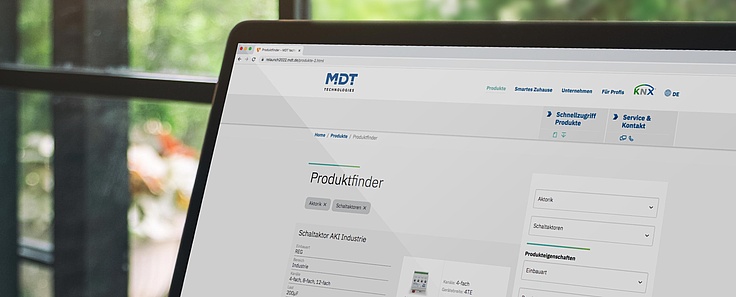
Choosing between over 300 KNX products is not easy. To help you find what you are looking for quicker, we have created a product finder.
References
MDT products have proven themselves millions of times over. We have gathered together implementation examples for smart building technology from numerous smart buildings for you.

